THREEPHASE TRANSFORMER BANKS
CONNECTIONS - OPEN DELTA
You will complete three-phase transformer bank diagrams for open Delta-open Delta, open Wye-open Delta systems.


In a previous module you have already covered the Wye/Delta bank and discovered that this bank has a characteristic of its own. That is, the H2 bushings are interconnected but not tied to the system neutral, thus giving us what is called a "Floating Neutral".
On Wye/Delta transformer bank configurations, a "floating neutral" connection has a common or neutral point, even though it is not grounded. As three phases are connected, each phase (and transformer primary coil) has a voltage across it of
4160
1.73 = 2400 volts
This is the same as would happen if the neutral were grounded.
Why then is the neutral not left grounded rather than floating it?
As mentioned, this connection is used to prevent bank burnout should a sectionalizing device between the station and the bank open. In other words, if the transformer bank's primary neutral (i.e., H2 bushings) were grounded, and if one of the supply phases loses power between the station and the bank, the two transformers still connected to the energized phases might overload as they try to supply the Delta-connected secondary.
Consider Figure 2. In it, one phase has lost power. The primary is connected as a standard Wye, with the 112 neutral connections grounded. The transformer connected to the isolated phase (and thus out of power) has been left off the diagram for clarity.
Figure 1
 |
As each transformer is connected between a phase and the grounded neutral, 2400 volts is applied across the primary coil. The output voltage of each transformer is 600 volts. Each phase of the secondary Delta-connected secondary gets its power from the bridged secondary connections between two transformers (voltmeter reads 600 volts between the positive of one transformer and the negative of another transformer). As a result, the voltage reading between secondary service wires is 600 volts. The secondary wires in Figure 1 have the following polarity markings:
1. Top phase is positive and negative polarity
2. Center phase has negative polarity
3. Bottom phase has positive polarity.
A voltmeter across any two phases will read between a positive and negative, indicating a full 600 volts.
This is fine. All motors, heaters, and air conditioners connected to the secondary wires will receive full voltage. However, in this case, there are only two transformers supplying a load originally requiring three transformers. Any equipment receiving full voltage will try to operate. The two transformers will continue to try and supply the current required to operate the equipment and will overload, likely burning out. Incidentally, it has been proven two transformers trying to supply the load of three only produce 57% of the original bank capacity.
A bank of three 100 kV transformers will supply a total of 300 KVA of power. If one transformer loses power (either from a fault on a supply phase or from the transformer itself burning out), the two remaining energized transformers only supply 57% of the original 300 KVA. In terms of KVA, there will only be
57 x 300 = 171 KVA
100
of power available. If the factory is running at full load (300 KVA), the two remaining transformers will overload and burn out trying to supply the required load.
To prevent this happening on Wye/Delta-connected banks, the "floating neutral" is used. If a supply phase loses power (i.e., blown fuse), the two remaining energized transformers operate as "single phase". They are incapable of developing full voltage. Therefore, any load connected will cease to operate. Look at Figure 2. (Only the two energized transformers are shown).
Figure 2

Look at the polarity markings. The transformer on the left has its 111 bushing connected to the top phase and is considered positive. Remember, polarities are instantaneous. Although phases in a Wye system are all considered positive, they are l20 out of phase. Only one phase is truly positive at any given instant. The other phases at that given instant must be negative with respect to the positive. The polarity markings shown in Figure 2 reflect this situation. Notice how the secondary phases are labeled as to polarity. A voltage reading will appear between the top secondary phase (positive) and the center and bottom phases (both negative). No voltage reading will appear between the middle and bottom phases, as both are the same polarity (negative). These two remaining transformers are unable to supply three-phase voltage.
Another interesting thing happens in this case. The rated secondary voltage, 600 volts, will not appear. The voltage will be lower. When all three transformers are connected and operating, each connected to a phase and the neutral floating, the voltage across each transformer primary coil in the three-phase connection is the phase to phase voltage divided by 1.73 or 4160 = 2400 volts.
1.73
However, with one primary phase out of power, we no longer have a complete three-phase system. There are now only two energized phases. The voltage across each transformer primary coil in this connection, then, is the phase-to-phase voltage divided by 2 or 4160 = 2080 volts.
2
If the voltage across each transformer primary coil is only 2080 volts, what will each transformer output voltage be? We can calculate this using the transformer ratio. These transformers have a ratio of 2400 = 4.1
600
If the input is 2080 volts, the output or secondary voltage will be 2080 = 520 volts.
4
This voltage is too low to operate 600 volt equipment. The transformer bank (the two remaining energized transformers) cannot overload and burn out.
The factory supplied by this bank will then call the Hydro and report a trouble call. The line crew will find the open supply phase and re-energize it. The bank will be supplied three-phase and will operate normally.
Note: A floating neutral brings with it some hazard, as it may be alive at line voltage (remember it is not grounded). Transformers used in this connection must have two ordinary bushings.
Often the most economical way to serve a small three-phase load is by the "open Delta" connection. This is usually fed from a Wye primary and is shown as an "open Wye/open Delta" connection. Only two primary phases and two transformers are needed to provide three-phase power. This connection supplies a three-phase load 86% of the total capacity of the two transformers.
Note: Two transformers rated 100 KVA each will produce a total of 86 x 200 = 172 KVA of power. Notice how this is
100
approximately the same power output the two transformers of an original three transformer bank would produce.
This connection could also be made if a trouble call on a Delta-connected service revealed one damaged or burned out transformer. If the bank were reconnected "open Delta", the two "good" transformers would supply part power, while a replacement for the damaged transformer was obtained and reconnected. The two remaining transformers will supply 86% of their total capacity or 57% of the original three-transformer bank capacity.
To connect this "open Delta" bank, the H2 bushings of the two transformers already interconnected to form the floating neutral must be connected to the system neutral. As shown earlier, this supplies each new connected transformer with phase to ground voltage and it will produce its rated secondary voltage.
Note: Only Delta-connected secondaries can be connected "open". Open Delta when referring to a transformer bank means two transformers supplying three-phase power.
The following diagrams show the "open Delta" secondary connections.
Figure 3
Remove Ground Straps on Delta Connection

Figure 3 is an open Wye/open Delta supplying a 600 volt Delta secondary.
Figure 4

Note: Remove Ground Straps on Delta Connections
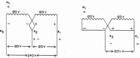
Figure 4 shows an open Wye/open Delta supplying a three-phase 240 volt Delta service.
Figure 5

Figure 5 shows open Delta/open Delta supplying a three-phase 240 volt Delta service.
THREE-PHASE TRANSFORMER
BANK DIAGRAMS
You will complete various combinations of three-phase transformer bank diagrams for:
WYE - WYE
WYE - DELTA
DELTA - DELTA
DELTA - WYE
OPEN DELTA - OPEN DELTA
OPEN WYE - OPEN DELTA
WYE - 240V DELTA WITH LIGHTING LOAD
WYE - 120/208V WYE WITH LIGHTING LOAD
- Spare schematic diagrams are available.
As a lineman, you will often install, maintain, and trouble-shoot three-phase transformer banks. Understanding how the bank works helps you install it to standard and fix it should trouble occur.
You already know the characteristics of both a Wye system and Delta system. In this module you will review basic transformer banks you learned in a previous module plus connect single phase services from 3 phase banks.
First, let's review the information you must have when connecting distribution transformers single phase or three phase. This information is found on the Name Plate, namely:
1. Primary or High Voltage - a transformer is rated to operate on a given primary voltage. If it is supplied with other than its rating, it will not give the rated secondary voltage.
2. Secondary or Low Voltage - is the voltage the transformer is rated to deliver if the primary voltage is supplied as rated on the nameplate.
3. If the transformers in a bank have tap changers, all transformers must be on the same percentage tap position to ensure the same output voltage on all three phases.
4. The impedances of banked transformers must be within 10% of one another. If not, the one with the lowest impendence (most efficient) will tend to hog the load or overwork.
When these four conditions are met, the transformers are ready to bank.
Most distribution systems used today are Wye systems with three phases and a neutral. Let's look at banking three transformers into a Wye primary.
A Wye system has the following characteristics:
1. Three phase, four wire
2. Phases may be said to have positive polarity
3. Neutrals are negative polarity and are grounded
4. There are two voltage levels, phase to ground and phase-to-phase, with the phase-to-phase value being 1.73 times the phase to neutral (ground) value.
5. Need to be the same polarity.
As you see, by following the characteristics of the particular system we deal with, and observing polarities, it is simple to connect three-phase transformer banks.
Figure 1 shows three transformers in position to be connected into a three-phase bank. C.S.A. states Hl bushing is always on the left when looking from the secondary side. This bushing is indicated on each transformer nameplate. The number 240° on the transformer is the transformer's rated primary voltage. For the transformer to operate properly, it must have the primary bushings (and primary winding) connected across lines giving that particular voltage.

2400/4160 VOLTS
Notice the size of the transformers in KVA has not been mentioned. The size of the transformers banked is usually the same, but not necessarily. The main criteria for banking are the transformers must have the same primary voltage and secondary voltage ratings. The importance of impedance matching was covered in a previous module.
Figure 2 shows the three transformers connected into the Wye system. Notice each transformer is connected to a different primary line. Remember, we are connecting to make a three-phase bank.
Figure 2

In the diagram, each transformer has been connected between a phase and the neutral. This is a phase to ground (neutral) connection. It supplies the transformer with its rated voltage, 2400 volts, since 2400 volts is the phase to ground voltage of this particular Wye system.
The lead from a primary phase to the transformer high voltage bushing does not always have to connect to Hl bushing. As a result, polarity markings are very helpful to ensure we connect the bank correctly. Figure 3 shows the phase lead for two of the transformers connected to the H2 bushing. One is connected to the third transformer's H1 bushing. All three transformers will operate. In this case, the correct voltage, 2400 volts, is still being applied to the primary windings. Notice tie position of the polarity markings.
Figure 3

With the polarity markings being different on the primary bushing, it is especially important to pay attention to hooking up the secondaries. The polarity of H1 determines the polarity of X1. Remember, there are two possible locations for X1 secondary bushing. It can be diagonally opposite H1 on an additional transformer, or directly opposite HI on a subtractive transformer. Checking the transformer name plate tells you the location of X1 bushing and the polarity of the transformer.
Keep in mind: H1 and X1 bushing on a transformer always have the same polarity. From these examples you see connecting a Wye primary is relatively simple. But, you must keep the characteristics of the Wye system in mind.
1. Connect the transformer primary winding across the leads that supply the correct voltage the transformer is rated for.
2. Each transformer connects to a different phase.
3. Phases have positive polarity, neutrals are negative and grounded.
In Figure 4, secondary bus wires, transformer secondary coils, and secondary bushings are shown. Also shown is the location of the X1 bushing. From the location of X1 bushing, these must be additive transformers.
The secondary coil and its voltage rating, 347 volts, is shown. We will always show the secondary coil or coils, as some transformers have more than one inside to be dealt with.
On the X2 secondary bushing is shown a ground strap. This connects the X2 bushing to the transformer case. It also keeps the bushing grounded via the transformer case ground.
Figure 4A

There are four secondary wires shown. Three are marked as phases and one as the neutral. This indicates the secondary will be connected Wye. Also, two voltages are shown, 347/600 volts. If 347 is multiplied by 1.73, the answer is 600. Therefore, this is a Wye system where 347 volts is the secondary phase to ground voltage and 600 volts is the secondary phase-to-phase voltage. Each transformer secondary output is rated 347 volts. Each transformer will supply one secondary phase. When the three transformers have been connected, the phase-to-phase voltage is calculated as follows:
transformer output (347) x 1.73 = phase to phase voltage
Each transformer output (secondary voltage) must equal the phase to ground voltage required on the secondary bus.
Figure 4B

In the Wye system, phases are considered positive; neutrals are negative and grounded. In Figure 4, Hi connected to a primary phase is positive; therefore, X1 is also positive. The positive secondary phase leads come from the positive X1 secondary bushing. The X2 secondary bushing is negative (opposite polarity from X1) and connects to the secondary neutral. Neutrals are grounded. This is indicated by the ground symbol on the neutral line and by the individual grounded tank straps.
The secondary lead from each transformer bushing connects to a X1secondary phase. It will read 347 volts (the transformer output) to neutral. Since each transformer connects to a different phase, we have a three-phase system. Voltage phase to phase in this system is the phase to ground voltage, 347 volts, multiplied by 1.73 to give 600 volts as indicated by the diagram.
Another common Wye secondary voltage is 120/208 volts. This service is used where 208 volts phase to phase is required to supply three-phase motors and 120 volts is required to run small drills, power hand saws, clocks, radios, light bulbs, etc.
Let's examine this transformer bank connection. The transformers used in this bank are standard-single phase 120/240 volt household distribution transformers.
Figure 5

Now we connect the secondary. Each transformer' output must match the phase to ground reading required by the service. In this case, we need 120 volts, so the two secondary coils in each transformer must be put in parallel for 120 volt output.
Do you remember how this is accomplished? Two connections are shown in Figures 5a and 5b, involving the two secondary coils in a transformer. One connection is a series connection (voltages add) and the output will be 120/240 volts. The other connection is a parallel connection (voltage stays the same) and the output is 120 volts. Polarity markings have been shown to help in making these connections. For a parallel connection, you connect positive-to-positive and negative-to-negative.
Figure 5a Figure 5b
 |
In our 120/208 Wye secondary, each transformer output must match the services phase to ground voltage, 120 volts. Each transformer will have its secondary coils connected in parallel inside the transformer for an output of 120 volts. When the transformers are banked three phase, the phase to phase voltage will be: 120 x 1.73 = 208
R ~ + 7200/12,400 VOLTS
In our 120/280 Wye secondary, each transformer output must match the services phase to ground voltage, 120 volts. Each transformer will have its secondary coils connected in parallel inside the transformer for an output of 120 volts. When the transformers are banked three phases, the phase-to-phase voltage will be: 120 x 1.73 = 208.

Figure 6 shows the internal transformer coils put in parallel so each transformer output will be 120 volts. The positive lead comes out the X1 bushing. The negative lead comes out the grounded X2 bushing to become the neutral. For 120 volt output, you use the grounded center bushing, X2, and the X1 bushing.
As a lineman, you rely on what you see to help determine many situations. For instance, if you see a standard distribution transformer with three secondary leads, one from the center bushing and one from each of the other bushings, you may assume that transformer is wired for 120/240 volt output. If you see one bushing taped up without a lead from it and leads coming from the other two bushings, you may assume the transformer is wired for 120 volts. If you see two leads, one from each outside bushing, and the center bushing taped up, AND the tank strap removed, you may assume the transformer is wired for 240 volt output (Figure 1).
Figure 7

Note: You should NEVER go on assumption. Always check the nameplate and take a voltage reading to be sure your prediction is correct. Assumptions can be deadly!
As we are dealing with Wye systems, let's connect another system you may encounter. It is a 240/416 Wye secondary, often used to supply apartment buildings. Notice the phase to ground (neutral) voltage of this bank. What does each transformer output have to be?
If you said 240 volts, you are correct. Where, then, does the 416 volts come from? Since 416 is the phase to phase voltage in this Wye system, 416 must equal 240 x 1.73. It does! this is a characteristic of all Wye systems.
Figure 8 shows this transformer bank, a Wye/Wye bank, because the primary is fed from a Wye system and the secondary is a Wye system.
Figure 8

Note: The X2 bushing is "alive" at 120 V to ground.
Notice how all the polarity markings are used to advantage. They help us to place the internal transformer secondary coils in series for 240 volt secondary output. They also identify which bushing of each transformer is positive and a phase lead, and which are negative and neutral lead. If the ground or tank strap was long enough, it could be removed from X2 and repositioned on X3. However, you will find in the field these straps are only long enough to connect to X2 bushings.
Figure 9 illustrates how one secondary ground strap was left on X2 and X3 was connected to neutral.
Figure 9

In the previous examples of the Wye primary and Wye secondary banks (often referred to as Wye/Wye banks), all transformers used were additive polarity. In Figure 10, two subtractive transformers have been banked with one additive transformer. By using polarity markings throughout, you see the bank still exhibits all the characteristics of a Wye system.
Figure 10

As you know, each primary lead will always have a fused cutout and lighting arrester for line and transformer protection respectively, even though we have not drawn them in the diagrams.
If you have any questions about the Wye primary, Wye secondary connections, ask the Instructor before progressing.
In previous examples of the Wye primary and Wye secondary (often referred to as Wye/Wye banks) banks, all transformers used were additive polarity. In Figure 11, two subtractive transformers have been banked with one additive transformer. By using polarity markings throughout, you see the bank still exhibits all the characteristics of a Wye system.
Figure 11

Delta-connected primary systems are quickly fading from distribution systems. As you remember from the previous module, there is no neutral or ground connection. A transformer connected in this system must be connected between two phases to operate. As it is connected this way, both primary leads must have their own cutout switch and lightning arrester. This makes the Delta primary connected transformer more costly to install. Also, since there is no ground connection in the Delta system, an energized phase in contact with ground does not always cause circuit protection devices to open. This is illustrated in Figure 1.
Figure 1
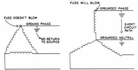
A Delta schematic is shown on the left and a Wye schematic on the right. A ground is shown on a phase in each system. Since electricity always seeks the quickest return path to the source of supply, only the fuse on the grounded Wye phase will operate. The Delta system has no electrical connection with ground. Consequently, the grounded phase has no entry into the system for current to flow through. A Wye system reacts quickly to ground faults, since it is a grounded system.
Before we look at connecting the Delta primary and Delta secondary, let's review the characteristics of Delta systems. As with the Wye connections, we use the Delta characteristics to ensure we make our connections correctly:
The Delta system has:
- Three phases, three wires
- One voltage, phase to phase
- Phases have positive negative polarity due to "bridging"
of coil ends
- No grounds in this system
Figure 2
30 3-Wire Delta System

Figure 3 shows three transformers ready to be banked into this Delta system. Notice the transformer primary coil rating shown. This indicates each transformer wants 4160 volts primary to make it work properly. Where do we have 4160 volts in this system? Between any two phases.
Figure 3

It is easy to connect the transformer primaries. Just make sure each transformer is connected between two different phases, i.e., no transformer connected between the same two phases as another.
Figure 4 shows this connection. Notice the polarity marks used. The transformer on the left gets its 4160 voltage between the positive portion of the top phase and the negative part of the middle phase. The center transformer, energized 1200 after the one on the left, gets its voltage between the positive of the middle phase and the negative of the bottom phase. The last transformer, on the right, gets its voltage between the positive part of the bottom phase and the negative part of the top phase.
Figure 4

Both top and bottom diagrams in Figure 4 are the same electrically. In the bottom diagram, the H2 of the left transformer has been connected to the Hi of the middle transformer, and a single lead is taken up to the center phase. This has also been done between the middle and right-hand transformers. You often do this in the field to save a bit of wire and eliminate two cutouts and arresters. Notice in both diagrams how no two transformers are connected between the same two phases, and we have a three-phase connection.
Figure 5 shows these transformers connected to the secondary lines to provide a 600-volt Delta secondary. Each transformer output (secondary coil rating) is 600 volts, since, in the Delta connection, each end of a coil supplies two different phases.
Polarity markings have been affixed to the secondary bushings. The positive of one transformer has been connected to the negative of the next transformer. Each phase lead comes from the bridged connection and will have positive negative polarity. Remember back in the Delta schematic - the positive of one coil was connected, or bridged, to the negative of the next. From this connection came the positive negative phase lead (Figure 6).
The secondary wires exhibit all the characteristics of the Delta system:
- Three phases, three wires
- Phases have positive and negative polarity
- No ground connection
- One voltage, phase to phase
Figure 5

Figure 6

We mentioned earlier the visual identification you use to help you.
Specifically, we looked at the connection of the secondary leads coming from distribution transformers, i.e., 120/240 volt, 120 volt, and 240 volt with three (or four) secondary bushings, and whether or not the ground strap on the center bushing was connected.
To expand on this idea, consider: of the most widely-used distribution transformers, those with only two secondary bushings (indicating only one secondary coil inside) are either wired for 347 volt or 600 volt output. The transformer wired for 347 volt output, since it is used to supply Wye secondaries, usually has a tank or ground strap connected to one secondary bushing.
A transformer wired (or wound) for 600 volt output will not have a ground strap connected to either secondary bushing. This transformer will always have two primary bushings.
Note: Most new transformers designed to work or, Wye primary systems are built with only one high voltage bushing. This helps reduce the cost of the transformer. A new transformer wired for 600 volt output always has two primary bushings, even though it will connect to a Wye primary. This is because it often uses a connection called a "Floating Neutral". We look at this connection in a later module.
Another visual you will use is the way the secondary transformer leads connect to the secondary bus or service wires. If one live lead from each transformer feeds only one leg of the bus or service, this is a Wye-connected secondary with the other transformer lead connected to the service neutral. If there is a "bridging" between transformer secondary bushings from which a lead connects to the bus or service leads, this is a Delta-connected secondary. Always check your predictions by looking at the transformer nameplate or by using a voltmeter.
We have stated in a Delta there are no ground connections. Most household voltage (120/240) distribution transformers are equipped with a ground strap connected. These same transformers are used to supply 120 volt Delta 240 V loads. The following diagrams show how this is done eliminating the ground strap connection.
Figure 7

In Figure 7, the secondary voltage wanted was 120 volt Delta. The transformer internal coils were put in parallel (positive to positive, negative to negative) so each transformer output would be 120 volts. The positive lead from one transformer was "bridged", or connected, to the negative lead of the next transformer, A lead was brought, from this connection, down to the secondary wires. The ground straps were removed from the X2 bushing of each transformer.
Figure 8 shows the connection for a 240 volt Delta secondary.
Figure 8
 |
In Figure 7, the internal secondary transformer coils have been connected in series to provide 240 volt output. The positive lead from one transformer has been bridged to the negative lead of the next transformer. A lead has been brought down, from this bridge, to the secondary wire. The ground straps were removed from the X2 bushings.
Each transformer output is 240 volts. The Xl lead feeds to one secondary wire and the X3 lead feeds another, A a result, a voltage of 240 volts appears across the secondary wires.
Let's look at the reason for removing the ground straps. To illustrate, Figure 9 has been drawn in Delta configuration, showing the transformer secondary coils.
Figure 9

You can see with ground straps left on the X2 bushings, now ground connections, short out between all three transformer windings. One ground would cause no problem, as there would be no return path through ground back to the system. However, with more than one ground, as illustrated, short circuit current has access back into the system.
Remember, no grounds in the Delta system.
All the transformers used as examples in this section have been additive polarity. Figure 10 shows a 120 volt Delta secondary connected using one subtractive and two additive transformers. By using the polarity markings, the proper connection can easily be made. Follow the connections and see how they are made.
Figure 10
 |
Let's look at another transformer bank connection. This has a
Delta-connected primary and a Wye-connected secondary. This type of bank is commonly referred to as a Delta/Wye bank.
You already know how to connect the primary of the transformer into a Delta system and how to connect secondaries into a Wye system. The Delta/Wye bank is a combination of the two.
Figure 11 shows such a connection. The primary is 8320 volts Delta and the secondary is 120/208 Wye. Polarity markings are shown to facilitate the paralleling of internal transformer coils and for connecting the phase leads.
Figure 11

Since the primary voltage is 8320 V phase to phase, transformers have been selected with a primary coil rating matching this voltage. The primary is connected between phases. No two transformers have been connected between the same two phases. The primary is connected Delta. The transformers will supply their rated secondary voltage.
Follow the individual polarity markings. The internal transformer secondary coils have been out in parallel so the transformer output will be 120 volts. This matches the required phase to ground voltage of the secondary service. The secondary leads have been connected to the four wire service. This ensures the service takes on the characteristics of the Wye system: three phase, four wire; phases have positive polarity, neutrals are negative and grounded; there are two voltages, phase to ground (neutral) of 120 volts, phase to phase of 120 x 1.73 = 208 volts. There is no real concern the grounded secondary neutral will have any adverse effect on the Delta primary, as there is no electrical connection between the primary circuit and the secondary circuit. Remember, the secondary is energized by Induction between the primary winding and the secondary winding, not by an electrical connection.
Figure 12, shows another Delta/Wye bank connected to supply 347/600 volts secondary. There has been one subtractive transformer used as a reminder the only difference between it and the two additive ones is the location of the X1 bushing. This information is on the nameplate. In the diagram we use positive/negative polarity markings to connect correctly.
Figure 12

As you can see, by following the characteristics of the particular system we deal with, and observing polarities, it is simple to connect three-phase transformer banks. You will look at another commonly-used transformer bank in the next module, but it will be connected following the same principles you have already learned.
You have already covered many of the standard three-phase banks used throughout the province. You know that during connection and operation banks exhibit definite Wye or Delta characteristics, depending on the secondary voltage required.
A common secondary voltage in large factories is 600 volt three-phase Delta. Its voltage level is five times higher than 120 volts.
Consequently, it can supply power at a far lower current level than a single-phase 120 volt system. Since 600 volt Delta does not have a neutral in its connection, there are small transformers (called dry transformers) inside the factory to convert from the 600 volts to supply 120/208 volts for lights and small tools.
You have connected the 600 volt Delta secondary fed from a Delta primary. Now, we look at this secondary connection fed from a Wye This connection could be as a standard Wye primary and Delta
Some utilities do connect this way. However, most utilities and Ontario Hydro connect this bank with what is called a "Floating Neutral".
The H1 bushing of each transformer is connected to an individual phase conductor (Figure 1).
In the Wye/Delta bank, the H2 high voltage bushings are interconnected and left floating - they are connected to one another but not connected to the system or primary neutral or ground. This prevents possible bank burnout when one sectionalizing device (line fuse, recloser, etc) between the station and the bank opens.
Figure 1
 |
Note: A "floating neutral" brings with it some hazard, as it may be alive at line voltage (remember it is not grounded).
Transformers used in this connection must have two primary bushings.
This connection has a common or neutral point, even though it is not grounded. As three phases are connected, each phase (and transformer primary coil) has a voltage across it of
4160
1.73 = 2400 volts
This is the same as would happen if the neutral were grounded.
Why then is the neutral not left grounded rather than floating it?
As mentioned, this connection is used to prevent bank burnout should a sectionalizing device between the station and the bank open. In other words, if one of the supply phases loses power between the station and the bank, the two transformers still connected to the energized phases might overload as they try to supply tie Delta-connected secondary.
Consider Figure 2. In it, one phase has lost power. The primary is connected as a standard Wye, with the H2 neutral connections grounded. The transformer connected to the isolated phase (and thus out of power) has been left off the diagram for clarity.
Figure 2

As each transformer is connected between a phase and the grounded neutral, 2400 volts is applied across the primary coil. The output voltage of each transformer is 600 volts. Each phase of the secondary Delta-connected secondary gets its power from the bridged secondary connections between two transformers (voltmeter reads 600 volts between the positive of one transformer arid the negative of another transformer). As a result, the voltage reading between secondary service wires is 600 volts. The secondary wires in Figure 2 have the following polarity markings:
1. Top phase is positive and negative polarity
2. Center phase has negative polarity
3. Bottom phase has positive polarity.
A voltmeter across any two phases will read between a positive and negative, indicating a full 600 volts.
This is fine. All motors, heaters, and air conditioners connected to the secondary wires will receive full voltage. However, in this case, there are only two transformers supplying a load originally requiring three transformers. Any equipment receiving full voltage will try to operate. The two transformers will continue to try and supply the current required to operate the equipment and will overload, likely burning out. Incidentally, it has been proven two transformers trying to supply the load of three only produce 57% of the original bank capacity.
Example: A bank of three 100 kV transformers will supply a total of 300 KVA of power. If one transformer loses power (either from a fault on a supply phase or from the transformer itself burning out), the two remaining energized transformers only supply 57% of the original 300 KVA. In terms of KVA, there will only be
57
100 x 300 = 171 KVA
of power available. If the factory is running at full load (300 KVA), the two remaining transformers will overload and burn out trying to supply the required load.
To prevent this happening on Wye/Delta-connected banks, the "floating neutral" is used. If a supply phase loses power (e.g., blown fuse), the two remaining energized transformers operate as "single phase". They are incapable of developing full voltage. Therefore, any load connected will cease to operate. Look at Figure 3. (Only the two energized transformers are shown).
Figure 3

Look at the polarity markings. The transformer on the left has its H1 bushing connected to the top phase and is considered positive. Remember, polarities are instantaneous. Although phases in a Wye system are all considered positive, they are 120° out of phase. Only one phase is truly positive at any given instant. The other phases at that given instant must be negative with respect to the positive. The polarity markings shown in Figure 3 reflect this situation. Notice how the secondary phases are labeled as to polarity. A voltage reading will appear between the top secondary phase (positive) and the center and bottom phases (both negative). No voltage reading will appear between the middle and bottom phases, as both are the same polarity (negative). These two remaining transformers are unable to supply three-phase voltage.
Another interesting thing happens in this case. The rated secondary voltage, 600 volts, will not appear. The voltage will be lower. When all three transformers are connected and operating, each connected to a phase and the neutral floating, the voltage across each transformer primary coil in the three-phase connection is the phase to phase voltage divided by 1.73 or 4160 = 2404 volts.
1 .73
However, with one primary phase out of power, we no longer have a complete three-phase system. There are now only two energized phases. The voltage across each transformer primary coil in this connection, then, is the phase-to-phase voltage divided by 2 or 4160 = 2080 volts.
2
If the voltage across each transformer primary coil is only 2080 volts, what will each transformer output voltage be? We can calculate this using the transformer ratio. These transformers have a ratio of 2400 = 4.1
600
If the input is 2080 volts, the output or secondary voltage will be 2080 = 520 volts.
4
This voltage is too low to operate 600 volt equipment. The transformer bank (the two remaining energized transformers) cannot overload arid burn out.
The factory supplied by this bank will then call the Hydro and report a trouble call. The line crew will find the open supply phase and re-energize it. The bank will be supplied three-phase and will operate normally.
The following two Wye/Delta banks are examples of using the "floating neutral". We could also add this statement to our list of characteristics of Wye and Delta systems:
- Wye/Delta banks have a floating neutral
Figure 4

Figure 5

Often the most economical way to serve a small three-phase load is by the "open Delta" connection. This is usually fed from a Wye primary and is shown as an "open Wye/open Delta" connection. Only two primary phases and two transformers are needed to provide three-phase power. This connection supplies a three-phase load 86% of the total capacity of the two transformers.
Note: Two transformers rated 100 KVA each will produce a total of
86 x 200 = 172 KVA of power. Notice how this is
100
approximately the same power output the two transformers of an original three transformer bank would produce.
This connection could also be made if a trouble call on a Delta-connected service revealed one damaged or burned out transformer. If the bank were reconnected "open Delta", the two "good" transformers would supply part power, while a replacement for the damaged transformer was obtained and reconnected. The two remaining transformers will supply 86% of their total capacity or 57% of the original three transformer bank capacity.
To connect this "open Delta" bank, the H2 bushings of the two transformers already interconnected to form the floating neutral must be connected to the system neutral. As shown earlier, this supplies each new connected transformer with phase to ground voltage and it will produce its rated secondary voltage.
Note: Only Delta-connected secondaries can be connected "open".
Open Delta when referring to a transformer bank means two transformers supplying three-phase power.
The following diagrams show the "open Delta" secondary connections.
Figure 6
Remove Ground Straps on Delta Connection

Figure 6 is an open Wye/open Delta supplying a 600 volt Delta secondary.
Figure 7

Note: Remove Ground Straps on Delta Connections
Figure 7shows an open Wye/open Delta supplying a three-phase 240 volt Delta service.
Figure 8

Figure 8 shows open Delta/open Delta supplying a three-phase 240 volt Delta service.
If you have any questions concerning the above information, ask the Instructor, If okay, do the Checkout now.
SINGLE PHASE LIGHTING SERVICE FROM A THREE-PHASE BANK
Normally a single phase customer is connected to a single phase transformer supplying 120/240 volts. If a three phase bank supplying 120/208 or 240 volt delta is nearby, often the most convenient way of supplying the single phase customer is from the three phase bank. The single phase service is often referred to as a "lighting service
240 Delta with 120/240 volt lighting service from on transformer:
If a single phase 120/240 volt lighting service is desired as well as the 3 phase 240 volt service, the tank strap on the center transformer is left connected and a secondary neutral brought out from this position.
This connection places a ground in the delta service. It is not a ground fault as mentioned above, but it will react and cause primary fuses to blow if a ground fault does appear on any leg of the 240 volt delta secondary.
Note: A voltage reading from the secondary legs of the service fed from this transformer to the secondary neutral will read 120 volts. A voltage reading from the secondary service leg that is not connected from this transformer, to the secondary neutral will read about 210 volts. This reading in normal, it does not indicate a problem with the service. This particular service leg is often referred to as the "Wild Phase" with respect to the "lighting service
120/208 Wve with 120/240 Volt Lighting Service from One Transformer
If a single phase 120/240 volt lighting service is desired as well as the 3 phase 120/208 volt service, the center transformer is left in series (internally) to provide both 120 and 240 volts. Usually it will have its KVA rating increased. The single phase service is not generally fed 3 wire 120/208 in place of 3 wire 120/240 as metering problems might arise using a standard 3 wire 240 volt meter. Its potential coil is rated 240 volts and two legs of the 208 volt service while being lower voltage leg to leg are also 120 electrical degrees apart (Figure 2).
1. If one fuse is blown, close the grounding switch and open outside cutouts first, the middle (lighting cutout) last.
2. If two fuses are blown, open the remaining cutout and then close the grounding switch. 3. Refuse the blown fuse. 4. Close middle fused cutout (lighting cutout) first, then two outside cutouts next, and making the fuse holders are closed properly. 5. Open the ground switch with load buster. 6. Check the secondary voltages. C. DE-ENERGIZING THE BANK (NO-FUSES BLOWN) –1. Close the ground switch.
2. Open outside fused cutouts first and the middle fused cutout(lighting control) last. 3. Open the ground switch. 4. Check for back feed. D. NOTES 1. Close lighting transformer cutout first if customer's main is closed. 2. Open outside transformer cutouts before the lighting transformer cutout if customer's main is closed. 3. If lighting transformer fuse is blown, do not close grounding switch until customer's main is open.4. Be aware that when one cutout is open on a wye delta bank, the bottom of the cutout will still be hot.
5. Ferroresonance is quite likely when energizing or de-energizing a 3-phase transformer fed through an underground cable where the cutouts are pole-mounted on the dip pole. 6. Ferroresonance is quite likely when a conductor is broken or opened on a 3-phase tap line, feeding on an underground wye delta bank. The longer the tap, the more likely the ferroresonance so long as there are no single-phase transformers between the open conductor and the bank. 7. Ferroresonance is not usually a problem under the following conditions: a) when using 3-phase switching b) when the transformers have secondary load connected c) when the bank is connected open wyeCalculating K.V.A. of 3 Phase Systems
Referring back to single phase calculations, we find Volt-amps = Line Volts x Line Amps
This is correct, as there is only one voltage and only one current. In a 3 phase system there are 3 voltages 120° apart, and the 3 resulting currents are also 120° apart.
To calculate 3 phase V.A., measure line to line voltage; also measure the current in any line. Multiply the product of line volts and line amps by the 3 phase correction factor 13 to find V.A.
This V.A. in a 3 phase system = Line to Line volts x Line amps x 1.73 Whether the system is WYE(STAR) or DELTA this rule applies.
K.V.A. = Line to Line volts x Line amps x 1.73
1000

Impedance Variations Allowable When Using 3 - 10
Voltage unbalance on a three-phase secondary service must not exceed 1% under the worst transformer loading condition
For reference purposes it is defined as:
Percent Voltage Unbalance =
Maximum Deviation from Average Voltage x 100%
Average Voltage
where the "average voltage" is the sum of the individual phase to neutral voltages (or the phase-to-phase voltages) divided by three.
Unbalanced secondary voltages may result from any of these causes: unbalanced primary supply voltages, unequal loads between phases, banked transformers having different tap settings, banked units of different rated kVA, or banked units of different impedances.
Assuming that unequal impedance is the only cause of voltage unbalance, the maximum variations in impedance that will result in a voltage unbalance of 1% on the secondary terminals are approximately as follows:

Example 1: Three single-phase transformers of the same kVA but having impedances of 2.25%, 2.25% & 1.5% are to be banked in a three-phase arrangement.
- Calculation:
- The average impedance = 2.25 + 2.25 + 1.5
3
- The deviations from the average impedance are:
2.25 - 2 = 0.25%
2.25 - 2 = 0.25%
1.5 - 2 = 0.5%
- The maximum difference is 0.5%
The three transformers may be used provided that the units are not loaded beyond 2.0 times their nameplate kVA rating.
Example 2: Units of 4%, 2%, 1.8% impedance have the same kVA rating. Can they be banked?
Deviations
Average Z = 2.6%
4% - 2.6 = 1.4
2 -2.6 = 0.6
1.8 - 2.6 = 0.8
The 4% unit exceeds the allowable limit at even the lightest loading. Therefore, these units cannot be banked and a substitute should be found for the 4% unit.
To parallel three-phase distribution transformer banks successfully, the four conditions listed under "Single-phase Paralleling" must be met. In addition, the angular displacements of the banks must be the same. For example, if voltage ratings, tap settings and frequency ratings are the same and percent impedance of one is between 92 1/2% and 107 1/2% of the other, a delta-delta bank can be paralleled with another delta-delta bank if both have 0° angular displacement. It can also be paralleled with a wye-wye bank that has 0° angular displacement. It cannot be paralleled with either delta-wye or wye-delta banks that have 3Q0 angular displacements.
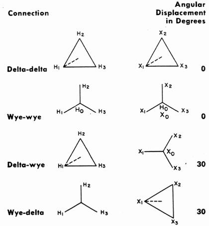 |
The angular displacements shown above are EEI-NEMA standard for three-phase transformers. Single-phase transformers can be connected in different ways in a three-phase bank as shown in the diagrams in the transformer connections section of this manual. The requirement for identical angular displacement must be met, however, for paralleling a three-phase transformer and a bank made up of three single-phase units, or for paralleling two banks both made up of single-phase units.
416 Transformer Installation – General Guidelines 1. It is the responsibility of the foreman or person in charge to check the nameplate on each transformer to be installed, making sure the nameplate voltage and the voltage specified by the workorder match.
Transformer nameplates shall be checked for polarity and percentage impedance when installing a three-phase bank or when changing out a defective transformer in a bank, in order that the transformers will bank properly. The phase rotation shall also be checked before any connections to the load are made.
3. Visually inspect each transformer for cracked bushings or oil leaks prior to installation and tag and report these to your supervisor or the customer with which work is being performed.
1. It is the responsibility of the foreman or person in charge to check the nameplate on each transformer to be installed, making sure the nameplate voltage and the voltage specified by the workorder match.
Transformer nameplates shall be checked for polarity and percentage impedance when installing a three-phase bank or when changing out a defective transformer in a bank, in order that the transformers will bank properly. The phase rotation shall also be checked before any connections to the load are made.
3. Visually inspect each transformer for cracked bushings or oil leaks prior to installation and tag and report these to your supervisor or the customer with which work is being performed.
4. During transformer installations, the neutral and/or ground attachments shall be made first. During the removal of transformers, the neutral and/or ground attachments shall be removed last.
5. Taps made from the high side of a transformer shall be made with an approved Hot Stick. 6. Transformer connections shall be tightened snugly when installing and transferring transformers. (Bending and repositioning existing secondary bus can cause loosening at lug points potentially resulting in future problems.) 7. It is the responsibility of the employee in charge to check (with a voltmeter) the secondary voltage of transformers prior to energizing the secondary conductors to the customers. 8. When installing or performing work on transformer banks, a rotation check shall be made and the secondary leads properly marked. It should be noted that if an existing transformer bank is being transferred or new bank is being installed, any previous lead marking installed by others should be ignored. (Linemen typically mark leads red, white, and blue for phase rotation – Installations made by commercial wiring electricians denote white and gray as neutral conductors – For this reason it is imperative that the customers neutral be identified before any secondary leads are connected.)