You will answer a series of review questions on the operation of a single-phase transformer, transformer loading, ratio and polarity checks.
Throughout your career you will work with transformers in a variety of ways installing them, checking them, and troubleshooting them. To work with transformers, you must understand how they operate so you can perform your job safely and efficiently. Let's look at how a transformer does its job.
Transformers have no moving parts. They transfer AC power from one winding to another by electromagnetic induction. Typically, the output power of a transformer is at a different voltage and current than the power supplied. A step-down transformer receives AC power at a given voltage and delivers AC power at a lower voltage. A step-up transformer increases the voltage level.
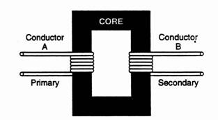
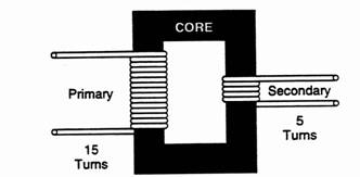
In its simplest form, a transformer consists of three components: a primary winding, a secondary winding and a core. The conductor labeled A in Figure 1 is the primary coil. Shaping this conductor into a coil increases its magnetic field. The second conductor labeled B, is the secondary coil. This conductor is coiled to increase its exposure to the primary's magnetic field. Both coils are usually wound around a metal core, which concentrates and directs the magnetic field. Current is sent through the primary side of the transformer. The changing magnetic field created around the primary coil induces a voltage in the secondary coil.
Figure 1
There is a direct relationship between the number of turns in each winding and the amount of voltage changed from primary to secondary. For example, if there is the same number of turns in both windings, the primary's magnetic field will have the same number of conductors to cut across. As a result the induced voltage will be the same as the applied voltage, and nothing changes. If there are more turns in the secondary winding then in the primary winding, the primary's magnetic field has more conductors to cut across. The induced voltage is greater than the applied voltage.
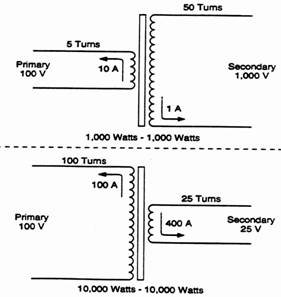
Figure 2 shows how a typical step-up transformer is built. There are more turns in the secondary coil than in the primary coil. The voltage output from this, and all other transformers, is determined by the ratio between the number of turns in the primary coil and the number of turns in the secondary coil. In the transformer represented in Figure 2, there are five turns in the primary coil and ten turns in the secondary coil. Because there are twice as many coils on the secondary side as on the primary side, the output voltage is twice the input voltage. An increase in voltage causes a corresponding decrease in current. The output current in this example is half the input current. When voltage is doubled, current must be halved so the power (voltage times current) going into the transformer's primary side is equal to the power coming out of the secondary side.
Figure 2
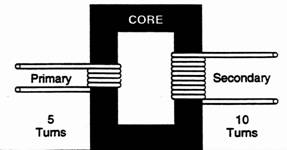
Figure 3 shows how a typical step-down transformer is set up. In this transformer, the primary coil has three times as many turns as the secondary coil. Therefore the secondary voltage is only one-third that of the primary. Power-in must equal power-out, so the output current is three times the input current. (This transformer steps down voltage, so the current increases.)
Figure 3
The magnitude of the voltage induced in a transformer secondary depends upon the turns ratio of the transformer. Turns ratio is a comparison between the number of turns on the primary winding and the number of turns on the secondary winding. For example, if a transformer has 400 turns on its primary winding and 100 turns on its secondary winding, the turns ratio is 400:100, or 4:1. If a transformer has a 4:1 turns ratio, the ratio between its primary and secondary voltages will also be 4:1. With a 100-volt primary voltage, the secondary voltage will be 25 volts. This results in a step-down transformer: the voltage delivered by the secondary is lower than the primary voltage.
A step-up transformer has a larger number of turns on the secondary than on the primary. For example, if a transformer has 50 turns on the primary winding and 250 turns on the secondary winding, its turns ratio is 50:250, or 1:5. The secondary voltage is five times as great as the primary voltage. If the primary is energized with 100 volts, the secondary delivers 500 volts.
A useful concept for understanding transformer turns ratio states the primary and secondary windings of a transformer always have the same number of volts per turn. In the example used above, the primary winding has 50 turns and a voltage of 100 volts: two volts for every turn on the winding. The secondary winding has 250 turns and a voltage of 500 volts: two volts for every turn on the winding.
Transformers also have equal ampere-turn values for both the primary and secondary windings. If current flow through a 50-turn primary winding is measured to be 10 amperes, the primary winding has an ampere-turn value of 500 ampere-turns. If the secondary winding has 250 turns, then its current is 2 amperes.
500=2
250
This example shows the relationship between primary and secondary currents is opposite to the relationship between primary and secondary voltages. A transformer with a 1:5 turns ratio will have a secondary voltage five times greater than the primary voltage. The secondary current will be only one-fifth of the primary current. In mathematical terms, the ratio between the primary and secondary voltages is directly proportional to the turns ratio. The ratio between the primary and secondary currents is inversely proportional to the turns ratio. Figure 4 illustrates these relationships for both step-up and step-down transformer turns ratio.
Note:а Remember voltage will be produced on the primary side if
ааааааааааа there is an applied voltage across the secondary and vice
ааааааааааа versa.
Figure 4
 |
Before reading on, check your progress by working through these questions.
1. ааааааа List the three basic components of a basic transformer.
________________________________________________________________________________________________
2. ааааааа Power is supplied to the ______________ winding of a
ааааааааааа transformer.
3.аааааааааааааааааааа The _______________ winding is the output side of a
ааааааааааа transformer.
4. ааааааааааааааааааа A transformer with a 6:1 turns ratio is a ______________ transformer. (step-up; step-down)
5.аааааааа A transformer with a 1:2 turns ratio is a ______________ transformer. (step-up; step-down)
6.аааааааа If a transformer has a 4:1 turns ratio, its secondary voltage will be ________________ than its primary voltage.
ааааааааааа (higher; lower)
7.аааааааа If a
transformer has a
ааааааааааа (higher; lower)
8.аааааааа A transformer has a turns ratio of 8:1. It is primary voltage is 400 volts. What is the secondary voltage?
ааааааааааа ________________________________________________
9.аааааааа A transformer has a turns ratio of 10:1. Its secondary voltage is 240 volts. What is the primary voltage?
ааааааааааа ________________________________________________
10.аааааа A
transformer has a 5 ampere primary current and a 20
ааааааааааа ampere secondary current. What
is the turns ratio of the
ааааааааааа transformer?
ааааааааааа ________________________________________________
Check your answers with those at the end of this module.
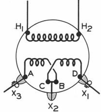
Some transformers are constructed to allow for adjusting the turns ratio by changing certain connections on the primary or secondary windings. These connections are called taps. Figure 5 shows one simple tap arrangement. The schematic illustrates a step-down transformer with a dual winding primary and a dual winding secondary.
Figure 5
 ааааааааааа
This transformer has two primary windings and two secondary windings. Each winding has a pair of terminals (each end of the winding is called a terminal). On the high voltage side (primary side) one winding has terminals designated H1 and H2. (CSA has made it an industry standard to label the high voltage terminal or bushing of a distribution transformer located on the LEFT, when looking at the transformer from the secondary side, as H1.) The terminals on the second high voltage winding are labeled H3, H4.
The letter designation for secondary terminals or bushing is X. In the transformer shown the two secondary windings have terminals labeled X1, X2 and X3, X4.
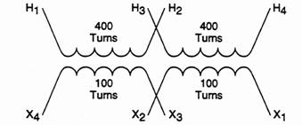
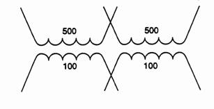
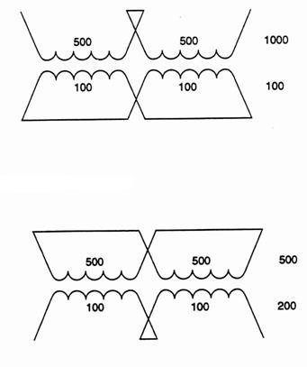
The advantage of a transformer equipped with dual windings is each pair of windings can be connected either in series or in parallel to yield the desired turns ratio. Figure 6 shows one example: the primary windings are connected in series and the secondary windings are connected in parallel.
Figure 6
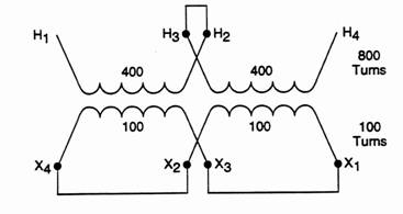
The illustration shows the necessary tap connections for this arrangement. On the high-voltage side, terminal H2 is connected to terminal H3. This puts the two high voltage windings in series with each other. Since each high voltage winding has 400 turns, the transformer primary now acts like a single primary winding with 800 turns. On the low voltage side, terminal X1 is connected to terminal X3 and terminal X2 is connected to terminal X4. Since the two 100-turn low voltage windings are connected in a single parallel bank, they will act like a single secondary winding with 100 turns. With an 800 turn primary and a 100 turn secondary, the transformer is now connected as a step down transformer with a turns ratio of 8:1.
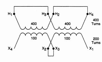
Figure 7
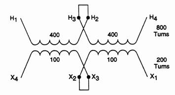 |
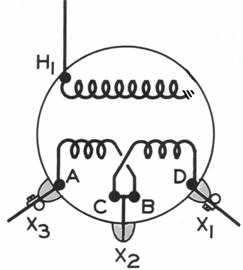
Figure 7 shows the same transformer with a different set of tap connections. In this example, the high voltage windings and the low voltage windings are in series.
In this arrangement, the high voltage windings are connected as they were in the previous example: connecting the two 400 turn primary windings in series yields a single high voltage winding with 800 turns. The two 100 turn low voltage windings are also connected in series: they act as a single secondary winding with 200 turns. By changing the tap connections on the secondary side of the transformer, the turns ratio has been changed. The ratio is now 800:200, or 4:1.
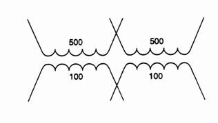
Figure 8
 ааааааааааа
Figure 8 shows a third tap configuration for the same transformer. In this case high voltage primary windings are connected in parallel. The two low voltage secondary windings are connected in series.
With this tap arrangement, the two 400 turn high voltage windings act as a single primary winding with 400 turns. The two 100 turn low voltage windings act as a single secondary winding with 200 turns. The new turns ratio is 400:200, or 2:1.
The preceding examples show how a transformer with dual primary and secondary windings can be connected to yield three different turns ratios. This is only one simple example of how a transformer's turn ration can be adjusted by making tap connections.
Here is another Review for you to complete.ааааа
1.аааааааа Draw in the tap connections for a 10:1 turns ratio.
 ааааааааааа
2.ааааааа Draw in the tap connections for a 2.5:1 turns ratio.
 ааааааааааа
3.аааааа Draw in tap connections for a 5:1 turns ratio.
 ааааааааааа
аааааааааа (There are two possible ways to obtain a 5:1)
Check your diagrams with those at the end of this module. If you had any incorrect diagrams, read over the information again.
Step Transformers
You have learned about single phase transformers that step down voltage from the distribution voltage to secondary voltage (e.g.) 4.8 kV / 120/240 V, and know they have what is called a primary winding and a secondary winding. Let's now look at another type of transformer that steps down voltage from one distribution level to another distribution level.
A transformer that steps down from one distribution voltage level to another is referred to as a Step Transformer. A typical single phase step transformer or rabbit may step down from 14.4 kV to 7.2 kV. This transformer has its primary winding rated at 14.4 kV and its secondary rated at 7.2 kV.
A transformer such as this would be used during voltage conversion to a higher supply voltage. A typical example of how the step down is used is given below. Only one single phase distribution line will be shown in the example.
Pike Electric, Inc. utility customer is undergoing a voltage conversion from 12.4/7.2 kV to 24.9/14.4 kV to better supply its customers. The amount of work involved to convert the whole line is far too great to do at one time. It is planned to convert other parts of the line to 24.9/14.4 kV at a later date. The other customers in the sections that haven't been converted will continue to be supplied at 12.4/7.2 kV. A Step Transformer is installed at the end of the section converted to 24.9/14.4 kV to feed the remaining customers in the unconverted section at 12.4/7.2 kV. The following diagram shows this:
Figure 9
![]()
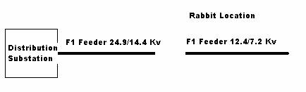
The switches that control the primary and secondary sides of the step down are located on the adjacent poles. You notice the transformer primary bushings are labeled H1 and H2 while the transformer secondary bushings even though they are supplying either 7.2 or 14.4 kV are labeled X1 and X2. Both H2 and X2 leads are connected to the line neutral, which runs continuous through the installation.
From your understanding of step down transformers, if the voltage is stepped down, the current will be stepped up to supply a given amount of power. Rabbits are rated 250 kVA and 75 kVA. Let's look at the current flow through a typical 250 kVA Rabbit operating at full load.
Example: The following schematic shows a 250 kVA step down rated 14.4 kV to 7.2 kV operating at full load.
Figure 10
At full load the primary draws 25OkVA =аа 250000а а=а 17.36 amps
аааааааааааааааааааааааааааааааааааааааа аааааааааааа 14.4kVааааа а 14400
The secondary suppliesаааааааааа 25OkVA аа=аа 250000а =а 34.7ampsаааа 7.2kVа аааааа 7200
If the customer utility installs step down, you will find additional information on their installation, in thier utility's standards.
Many distribution transformers are built with tap changers allowing you to alter the transformer's turns ratio to increase or decrease the secondary voltage. The need for altering the transformer ratio to increase voltage would be at the end of a long primary run if primary voltage was consistently low due to voltage drop in the primary line. The effect is to restore secondary voltage from an intolerably low or high level to near normal or within a tolerable range.
Any feeder, radiating from a substation is said to have a nominal voltage. But it is impossible to maintain this nominal voltage from the beginning of a line to the end due to variations in the voltage caused by voltage drop from a combination of the current in the line and the impedance of the line. The higher the current the greater the voltage variation from the beginning to the end of the line.
Most modern systems are designed and built with sufficient capacity to keep this voltage drop minimal. But older systems, especially rural systems, do have appreciable voltage variation in the feeder, due to long lines and high impedance.
Let's assume the voltage at a substation can be controlled so nominal voltage is maintained halfway out of the feeder. For this to happen the primary voltage at the feeder source (substation) would have to be higher than nominal and the voltage at the end of the feeder would be lower than nominal.
Due to this variation in voltage along the feeder, and since distribution transformers could be installed anywhere along this feeder, it is obvious transformers of the same rated primary and secondary voltage (i.e., turns ratio) will not produce the same secondary voltage at all locations on the feeder. The secondary voltage would be somewhat higher at the substation end than at the end of the feeder.
As mentioned before, on modern day systems, this voltage variation is not large enough to cause any real concern. A secondary voltage variation of plus or minus 5% is quite acceptable. Variations greater than this could be objectionable.
If transformers were manufactured with slight variations in turns ratio: purchased and installed at their proper location on the system; the secondary voltage level could be maintained quite evenly. This would create a major manufacturing, purchasing, and design problem since when system parameters and circuits changed the suitability of a transformer in a given location would change.
To overcome these problems, line voltage regulators are often used. If some voltage extremes still exist transformers may be ordered with a switch called a tap changer in the primary winding. This tap changer lets us change the number of turns in the primary winding thus changing the turns ratio making it possible to modify a transformer in the field to compensate for primary voltage variations. We can then maintain a reasonable level of secondary voltage at all points on the feeder.
Note: All tap changers on distribution transformers are off-load tap changers. They can be switched to a different tap only when the transformer is completely isolated.
The tap changer may be located inside the transformer or on the outside of the tank wall. The tap changer handle, when turned, causes the switch to make connections in the primary winding either cutting out some primary turns or adding them in, depending on whether we want the secondary voltage to be raised or lowered.
After a tap setting has been selected and made, the transformer is reenergized and voltage reading taken.
Study the transformer nameplate carefully to determine the characteristics of the tap changer. It indicates the number and percentage of each tap and the position the tap changer handle has to be in for a particular tap.
Normally distribution transformers are manufactured with either 4.5% taps or 2.5% taps. This means a tap change of one position varies the primary turns and adjusts the secondary voltage by 4.5% or 2.5% respectively.
All tap changers have a 100% tap position. This means when the tap changer is on this position, the ratio of primary to secondary turns correspond to rated nominal voltage.
Transformers manufactured with 4.5% taps usually have the tap settings arranged as follows: 91%, 95.5%, 100% and 104.5%. These tap positions and percentages correspond to the percentage the primary turns must be altered to give nominal secondary voltage.
The situation is similar with 2.5% tapped transformers. However these transformers have two 2.5% taps down (97.5% and 95%) and two 2.5% taps up (102.5% and 105%). A change of one tap position gives only a 2.5% voltage change instead of 4.5%. On 120/240 volt distribution transformers with 4.5% taps, one tap change alters the secondary voltage approximately 10 volts. On transformers with 2.5% taps one tap change alters the secondary voltage approximately 5 volts. Let's look at how this works.
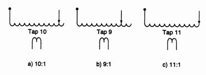
In the following diagram, a schematic of the transformer primary winding has 11 turns and a single turn secondary. There are three tap positions: 9:1, 10:1, and 11:1, (10% tap changer). The primary voltage is 100 volts for simplicity.
Figure 11
 ааааааааааа
In diagram (a) the tap position gives a 10:1 turns ratio. With a 100 volt primary, the secondary voltage will be 100аа =а 10 V
ааааааааааааааааааааааа аааааааааааааааааааааааааааааааааааааааааааааа 10
In diagram (b) the tap position has been turned down to give a 9:1 turns ratio. With a 100 volt primary, the secondary voltage will be
100 = 11.1 volts, an increase in secondary voltage.
а 9
In diagram (c) the tap position has been turned up to give a 11:1
turns ratio. With a 100 volt primary the secondary voltage will be
100 = 9 volts, a decrease in voltage.
а11
Note: taps upааааааааааааааааааааааа = a decrease in secondary voltage
аааааааааа taps downааааа = an increase in secondary voltage
From this it can be stated as taps are turned up, the secondary voltage comes down, and as taps are turned down, the secondary voltage goes up.
Example 1:а A customer complains of low voltage causing problems with electrical equipment. The line crew takes a voltage reading at the transformer and reads 110/220. The transformer is rated 2,400/120/240 on 100% taps. This means the transformer has a turns ratio of 10:1. The probable cause is heavy loading on the primary line. From the 10:1 turns ratio and 220 volts secondary, it is probable the primary line voltage is only 2,200 volts.
This transformer has 4.5% taps. The line crew knows each tap change will alter the secondary voltage 4.5%. They do some quick figuring to predict how many tap position changes must be made to bring the customer's voltage up to approximately 240 volts.
Here are their calculations:
1
tap changeаааааааааааа = 4.5% of 220 volts
аааааааааааааааааааааааааааааааааааа = 4.5 x 220
аааааааааааааааааааааааааааааааааааа а 100
аааааааааааааааааааааааааааааааааааа = 4.5 x 2.2
аааааааааааааааааааааааааааааааааааа = 9.9 volts
The voltage is presently 220 volts; one tap change down increases voltage 9.9 volts to 229.9 volts. This voltage is still low. The crew knows it must lower one more tap position adding 9.9 volts more to the 229.9 volts available from the first tap position change: 9.9 + 229.9 = 239.8 volts. This voltage is very close to nominal service voltage. The crew knows to lower the taps two positions below 100% or to 91% tap position.
Since taps are NEVER changed on a distribution transformer while it is energized, the crew isolates the transformer, lowers the tap setting two positions and reenergizes the transformer. They always take a voltage check to ensure their prediction was accurate. Yes, the voltmeter reads close to 120/240 volts and the job is complete.
Example 2:а A customer complains of high voltage on a 600 volt service. A voltage reading indicates 630 volts on the secondary. The transformer is set on 100% taps with tap settings of 2.5%. How many tap changes, and in what direction, must be made to bring the secondary voltage down to approximately 600 volts?
One tap change alters the secondary voltage by 2.5%. Secondary voltage is 630 volts. Therefore, one tap change results in 2.5 x
630= 15.7ааааа ааааааааааааааааааааааааааааааааааааааааааааааааааааааааааааааааааааа 100
From this, two tap changes give 31.4 volts. The taps must be turned up two positions to lower the secondary voltage to approximately 600 volts. (598.6 volts actual)
Complete the following review to monitor your progress.
1.аааааааа Tap changers alter the transformer turns ratio by cutting in or cutting out turns of the primary winding to alter
ааааааааааа secondary voltage.
ааааааааааа a)аааааааа Trueаааааааааааааааааааааааааааааааааа b) аааааа False
2.аааааааа A transformer is rated 2,400/240 volts, a 10:1 ratio. A voltage check on the secondary side reads 230 volts. This
ааааааааааа indicates the primary line voltage is ______ volts.
ааааааааааа a) 2,400аааааааааааааааааааааа c)аааааааа 2,500
ааааааааааа b) 2,300аааааааааааааааааааааа d)аааааааа 2,200
3.аааааааа Tap changers can be switched to a different tap only when the transformer is _____________.
4.аааааааа Turning the tap changer to a lower percentage tap will cause the secondary voltage to __________ (increase/decrease).
5.аааааааа A transformer rated 2,400/240 volts is on 100% tap position. The secondary voltage is only 230 volts. The tap settings are 2.5%. How many tap changes and in what direction must they be made to bring the voltage to approximately 240 volts?
________________________________________________________________________________________________________________________________________________
Check your answers with those at the end of this module. Any incorrect answers indicate you should review the information on tap changers.
Every transformer has an internal "impedance", which is the term used in AC circuits to describe the total opposition to current flow. It combines the effects of "resistance", inductance", and "capacitance"; and is symbolized by the letter "Z". (For ease of understanding, think of it as "AC resistance").
A transformer nameplate states the amount of impedance at full load as a percentage of the transformer's rated output voltage. For example, a transformer with an impedance of 2% will deliver 2% less than its rated secondary voltage when operating at full rated load. In other words a transformer with 2% impedance supplies 98% of its rated voltage at full load.
The importance of impedance to a lineperson occurs primarily when transformers are to be paralleled. For example, suppose there isn't a large enough transformer in stock to replace a defective customer unit. One solution would be to parallel two transformers of lower capacity, e.g., you could parallel two 25 kVA units to carry the customer's 50 kVA load.
When paralleling, it is important to use transformers having impedances as similar as possible. (Note that with transformers, impedance is usually expressed as "percent impedance", or "% Z"; and this value is shown on the transformer nameplate.) As load increase so does the importance of selecting transformers that have closely matched impedance, although under any loading conditions transformers matched to + or - 10% impedance will work well together.
The reason for requiring similar impedances can be explained using your knowledge of parallel circuits. For our purposes here, we can think of impedance in the same way as we did resistance in the module on series and parallel circuits. You recall that if two resistors having the same ohmic value are connected in parallel, the current will split equally between each. If the resistors are of unequal value then the one having the least resistance will carry the largest share of the current. The same thing happens with transformers in parallel, the one with the lowest impedance will carry a larger portion of the load. This could mean that even though the combined kVA ratings of the two transformers appear to be sufficient to handle the load, one of the transformers could still be overloaded and a burnout could result.
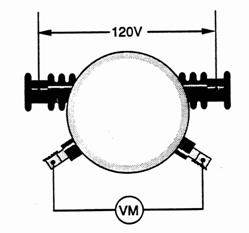
To perform a ratio check:
-аааааааааа input 120 volts across the HV (primary) coil (figure 12)
-аааааааааа verify the supply voltage with a voltmeter
-аааааааааа measure the voltage across the full LV (secondary) coil
-аааааааааа divide the secondary voltage into the primary voltage to determine coil ratio.
In the transformer shown in Figure 12 if the voltmeter across the secondary coil read 12 volts, the coil ratio would 10:1; if the voltmeter read 30 volts, the coil ratio would be 4:1.
Figure 12
When dealing with AC systems, polarity can sometimes be a deceptive term. Unlike DC equipment, AC components do not have terminals designated positive and negative: instead, each terminal changes from positive to negative and back again in the space of one cycle.
The polarity of transformer terminals is a question of instantaneous polarity. Figure 13 illustrates the concept for an instant in time when the voltage applied to H1 is at its peak positive value.
Figure 13
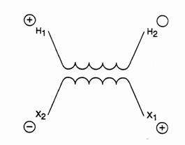
When terminal H1 is positive, terminal H2 be negative. On the low voltage side, however, there are two distinct possibilities: the low voltage terminal directly across from H1 may be either positive or negative at this given instant. This depends on the way the terminals have been brought out of the winding. In the example in Fig 13, the low voltage terminal directly across from ~ is negative when H1 is positive. The low voltage terminal diagonally across from H1 has the same polarity as H1: when H1а is positive, this terminal is positive. When H1 is negative, this terminal is negative.
In the standard terminology, odd numbered terminals have the same polarity as all other odd numbered terminals; even numbered terminals have the same polarity as all other even numbered terminals. In Fig 13, H1 and X1 will always have the same instantaneous polarity. H2 and X2 will also have the same instantaneous polarity.
The polarity of a transformer is typically given as either additive or subtractive. These terms are derived from a common test used to determine which high voltage and low voltage terminals have the same instantaneous polarity.
POLARITY CHECKааааааааааааааааааааааааааааааааааааааааааааааааааааааааааааааааааааааа
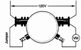
To perform a polarity check:
-аааааааааа install a jumper between the H1 high voltage bushing and the low voltage bushing directly opposite it (figure 14)
-аааааааааа input 120 volts across the HV (primary) coil
-аааааааааа verify the supply voltage with a voltmeter
-аааааааааа measure the voltage between the H2 HV bushing and the X1 LV bushing directly opposite it.
Note:аа If the transformer being checked is equipped with a ground strap at its X2 secondary bushing, remove before commencing the test.
Figure 14
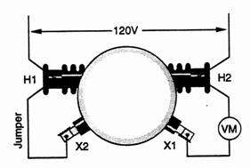 |
The transformer in Figure 14 has a ratio of 10:1 (step down). If 120 volts is applied across the high voltage terminals, 12 volts will be present across the low voltage terminals. If more than 120 volts is present across H2 and it's opposite low voltage terminal as read on the voltmeter, the low voltage terminal must have an instantaneous polarity opposite to H2 . If X1 has an instantaneous voltage of 12 volts, the difference in potential between the two terminals is 120 plus 12 or 132 volts. This arrangement is known as additive polarity. The primary and secondary voltages add together when the polarity test is performed. Conversely, if the voltmeter reads less than applied, in this case 108 volts (120 - 12) the transformer has subtractive polarity.
Transformer polarity is only a question of how the terminals themselves are arranged on the outside of the housing. On additive transformers, H1 and X1 are always diagonally across from each other. On subtractive transformers, аH1 and X1 are directly opposite each other. The polarity is indicated on the transformer name plate.
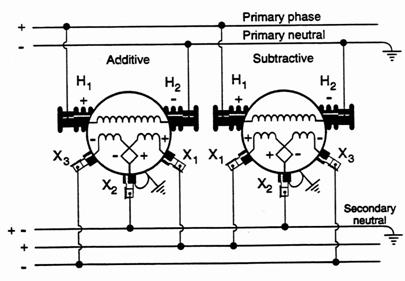
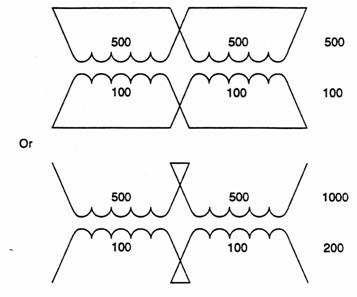
Transformer polarity is seldom important except when two or more transformers are being connected in parallel and three-phase banks. In this case, it is essential terminals being connected to the same line have the same instantaneous polarity. Figure 15 shows how an additive transformer and a subtractive transformer can safely be connected in a parallel bank.
Figure 15
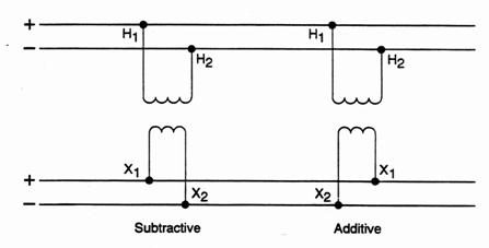 |
On the primary side, the H1 terminals of both transformers are connected to the same conductor. Both H2 terminals are connected to the other conductor on the primary side. On the secondary side, the X1 terminals are connected to the same line and the X2 terminals are connected to the same line. Even though one of the transformers is additive and one subtractive, they can be paralleled as long as terminals of the same polarity are tied together, regardless of their physical location on the transformers. If one of the transformers is connected in reverse, the two secondary voltage oppose each other, resulting in a dead short.
Several other requirements must be met before two transformers can be connected in a parallel bank. The transformers must have the same primary voltage rating, the same turns ratio, closely
matched impedance, and the same secondary voltage rating.
Primary and secondary voltage ratings must be matched to insure neither transformer is damaged by excessive voltage. Identical turns ratios are necessary for achieving desired secondary voltage across the common secondary lines. Impedances must be matched within 10% so both transformers share the load equally. Otherwise, the transformer with the lower impedance would perform more work than the transformer with the higher impedance. This could cause the transformer with the lower impedance to exceed its load rating, leading to overheating and possible damage to the transformer.
Many distribution transformers have a single primary winding, with two terminals or bushings and a dual secondary winding with three or four terminals or bushings. The dual secondary winding can be wired in series or in parallel by making internal connections to the three secondary bushings. Let's look at three typical secondary connections for this type of transformer.
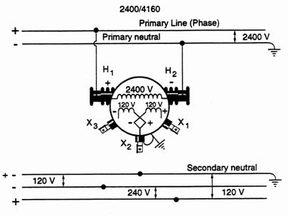
Figure 16
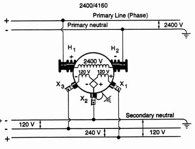
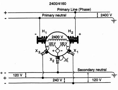
Figure 16 shows a three wire single phase output (secondary). The secondary windings (rated 120 volts) are connected in series. The two outboard terminals X1 and X3 are connected to the "live" secondary conductors. The center terminal X2 is connected to the secondary neutral conductor. You notice the neutrals are grounded, to keep them at ground potential. On the X2 bushing a tank strap is shown. It effectively grounds the X2 bushing via the transformer tank and case ground. This arrangement is used when a single distribution transformer supplies household power at two different voltages. For example, 240 volt equipment, water heaters, ranges, baseboard heaters, can be connected across the middle and bottom conductors. 120 volt equipment can be connected across the top and middle conductors or across the top and bottom conductors.
In Figure 16, instantaneous polarities are shown. The transformer is the additive type with X1 diagonally opposite H1. аAt X2 bushing the corresponding polarities of each secondary coil terminal are shown. With polarities, an individual coil has both a positive end and a negative end at any one time. The X2 bushing could also be referred to as the center tap of the total secondary windings. If X1 is positive at any given instant, X2 will be negative with respect to it. At the same time X1 is positive, X3 is negative so X2 is positive with respect to X3.
Figure 17
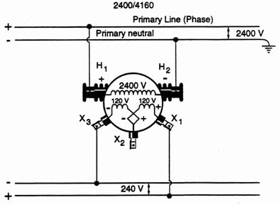
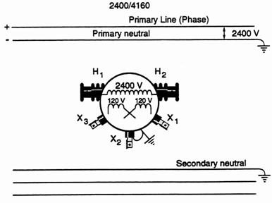
In Figure 17, both secondary windings are connected in series to deliver 240 volts. This secondary service requires 240 volts only, so the X2 bushing does not have a lead coming from it. The X2 bushing is used to provide a place for connecting the two secondary windings inside the transformer case.
Figure 18
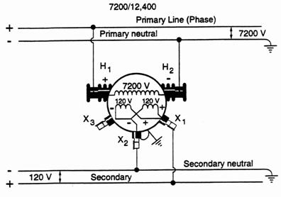
In Figure 18, the secondary windings are in parallel for a 120 volt output. Since 120 volt equipment requires a neutral conductor, the ground strap appears on the X2 bushing to ground the X2 lead keeping it at ground potential and making it the neutral conductor of the service. The two windings in parallel give the full transformer capacity (KVA). If only one winding was used, the voltage output would still be 120 volts. But the transformer capacity (KVA) would only be one-half of the full transformers KVA rating.
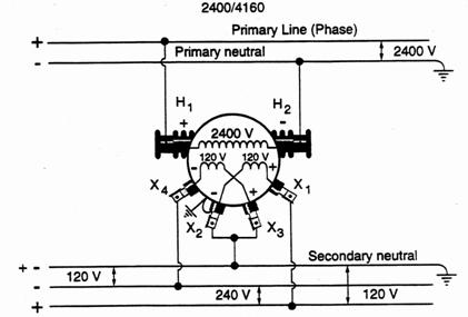
A transformer with four secondary bushings can be wired in any of these arrangements. Four bushing transformers are large and the internal lead size would not permit connecting the two secondary winding terminals at one X2 bushing. On a standard four bushing transformer, odd numbered terminals always have the same instantaneous polarity and even numbered terminals always have the same instantaneous polarity. The bushings are identified X1, X2
X3 and X4. For 120/240 volt operation an external jumper is
used to connect X2, X3 as shown in Figure 19.
Figure 19
 |
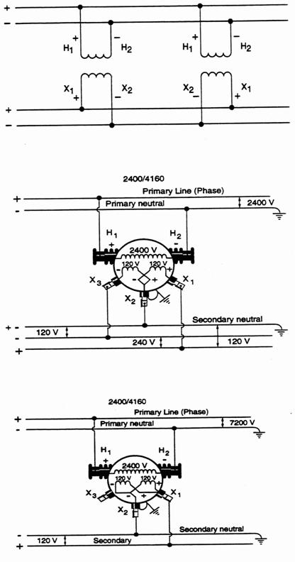
In all the preceding examples, the H1 high voltage bushing has been shown connected to the primary phase conductor and H2 connected to the primary neutral. This is the standard connection, although if the connection is reversed as in Figure 20 for practical reasons, the H1 bushing remains on the left and the X1 bushing will always have the same instantaneous polarity as H1.
Figure 20
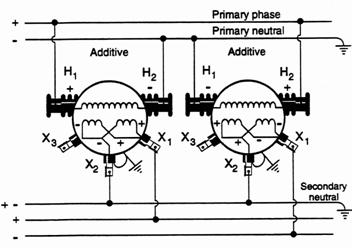
In a standard 120/240 volt secondary service, there is one positive live lead, one negative live lead and a positive-negative neutral lead. Occasionally it may be necessary to connect two transformers to a common secondary to provide adequate capacity. This might happen if a customer required 50 kVA of power and the utility only had two 25 kVA transformers available. When two or more transformers are connected to supply a common secondary service it is called banking the transformers. When banking transformers it is very important to connect leads of the same polarity together. A 120/240 volt service must have a positive-negative neutral, a positive live leg and a negative live leg. The following diagrams illustrate some methods used to bank two transformers providing 120/240 volts. In the first illustration (Figure 21) one additive and one subtractive transformer have been banked together with their interval secondary coils connected in series.
Figure 21
120/240 Volts
The important considerations here are ensuring the leads with the same polarity are connected to the same service lead.
The H1 bushings of each transformer have been connected to the live phase making them positive.
In the next diagram (Figure 22), both transformers are additive and have the live phase leads connected at opposite "H" bushings. By observing polarities, these transformers are easily banked.
Figure 22
Coils in Series
120/240 Volts
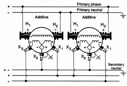 |
The live primary phase has been designated positive; the primary neutral is negative. Regardless of the polarity of H1, the X1 bushing will always have the same polarity as H1.
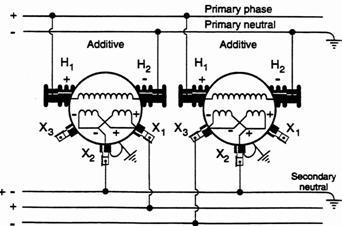
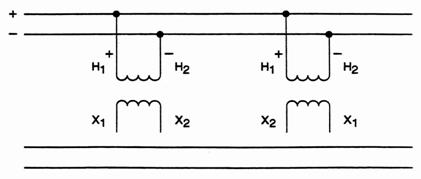
The following diagrams (Figures 23 and 24) show two banked transformers supplying 120/240 volts. The transformers have the secondary windings paralleled inside the transformers. By observнing polarities, the service wires still have a positive-negative neutral, a positive live lead and a negative live lead.
Figure 23
Coils in Parallel
120/240 Volts
 ааааааааааа а
аFigure 24ааааа
Coils in
Parallel
120/240 Volts
 |
Whenever paralleling or banking transformers alive into a common bus, use a voltmeter to determine which leads are the same polarity. Leads showing no reading are at the same potential and may be connected. Do not connect leads showing a voltage reading across them.
The two windings have been paralleled to give the full transformer capacity (kVA). If only one winding was used, the voltage output would still be correct, but the transformer capacity (kVA) would only be one-half of its kVA rating.
Complete the following review.
REVIEW #4
1.аааааааа The H1 high voltage bushing of a distribution transformer
ааааааааааа is always located on the _____________________
when looking at the transformer from the secondary side. (left, right)
2.аааааааа An additive polarity transformer has the X1 secondary bushing located __________________ opposite the H1
ааааааааааа high voltage bushing (directly, diagonally)
3.аааааааа Regardless of the location of the X1 bushing, additive or subtractive transformer, it will always have the same instantaneous polarity as H1.
ааааа a) Trueаааааааааааааааааааааа b)аааааааа False
4.аааааааа Whenever performing a ratio or polarity check of a distribution transformer, the low voltage test supply is always connected to the transformer _________________ voltage bushings. (high, low)
5.аааааааа During a ratio check of a distribution transformer, 120 volts supply was used. A voltmeter reading across the transformer secondary terminals read 6 volts. If the rated secondary voltage on the transformer name place is 240 volts, what is the transformer primary voltage rating?
ааааааааааа a) 2400V аааааааааааааааааааааааааааааа b)
4800V
ааааааааааа c) 7200V аааааааааааааааааааааааааааааа d)
14,400 V
6.ааааааа In the following diagram of a polarity check, the voltmeter reads 132 volts. This indicates the transformers have __________________ polarity. (additive, subtractive)
7.аааааааа Connect the additive and subtractive transformers into a parallel bank.
 |
|||
 |
|||
8.аа Connect this single phase transformer to provide 120/240 volts secondary output.
9.аа Connect this single phase transformer to provide 120 volt secondary output only.
Check your answers with those at the end of this module. If you had any incorrect answers read the information over again.
There have been quite a number of serious and fatal accidents in the field caused by employees failing to recognize the possibility of backfeed from banked transformers, transformer banks for three phase power, and also backfeed from privately owned generators.
Backfeed usually occurs when a customer generates power and it is fed back into Hydro's system. For example, during a power outage caused by a storm, a customer started up a gas generator. The generator was attached at the customer's panel box to supply the house with power. Unknowingly the customer also supplied power back onto the line and back to the transformer. The high side of the transformer was energized and thus created the hazard.
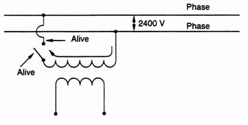
a)аааааааа A
conductor separated from its source of supply, will be
alive due to an electrical circuit
through a transformer
winding
connected to it when the other end of that winding is still connected to a
source of supply. Example: A transformer primary winding connected across two phases.
Figure 25
b)аааааааа A
transformer primary winding separated from its source
ааааааааааа of supply will be alive due to
an induced voltage if its
ааааааааааа secondary windings are in parallel with another
energized
ааааааааааа transformer. Example: Banked
transformer secondaries.
Figure 26
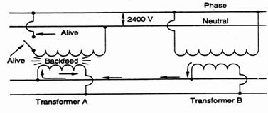
The example above illustrates a practice common with some utilities, of omitting the secondary bus break between adjacent transformers (Ring Bus), and the transformers may be separated by several pole spans.
The cutout of transformer "A" is OPEN but with transformer "B" still energized through its closed cutout, the primary winding of transformer "A" is still at primary potential due to backfeed through the secondary bus from transformer "B". Remember, a transformer will step up or step down, depending upon which way it is being supplied.
To avoid the hazard of backfeed, always isolate a transformer from its primary supply using live line tools and then remove the transformer leads at the secondary bus.
A backfeed may be caused by privately owned generators, such as those installed in rural farm services or industry. These generators are used to supply power in the event that normal supply is interrupted. If the generator is not installed according to the electrical safety code, it could energize the secondary bus which would induce a primary voltage on the line side of the customer's transformer and onto the primary line. Precautions against backfeed from customer's equipment are as follows:
a)аааааааа check with customers to be sure they have no means of creating backfeed
b)аааааааа lock
open customers main switch
c) аааааааа check
voltage on secondary bus
d)аааааааа disconnect the secondary leads from the bus wires.
Waste must be managed in your Utility in compliance with the legal requirements and with respect to a sound commitment to environmental protection.
PCB's or Polychlorinated biphenyls is a substance that is subject to waste management regulations. It is one of the major environmental issues now facing your Utility. Your Utility will have developed an approved handling and storage procedure for all suspect transformers containing PCBs. This procedure must be strictly adhered to. Ensure yourself that you are fully aware of these guidelines.
ааааааааааа 1.аааааааа primary winding, secondary winding, core
ааааааааааа 2.аааааааа primary
ааааааааааа 3.аааааааа secondary
ааааааааааа 4.аааааааа step-down
ааааааааааа 5.аааааааа step-up
ааааааааааа 6.аааааааа lower
ааааааааааа 7.аааааааа lower
ааааааааааа 8.аааааааа 50 volts
аааааааааа 9.аааааааа 2400 volts
ааааааааа 10.ааааааа 4:1
1.ааааааа 10:1 turns ratio
 ааааааааааа
2.аааааааа 2.5:1 turns ratio
3.аааааааа 5:1а turns ratio
>REVIEW #3
ааааааааааа 1.аааааааа a)а True
2.аааааааа b)а 2,300
ааааааааааа 3.аааааааа isolated
ааааааааааа 4.аааааааа increase
ааааааааааа 5.аааааааа 2 taps down 230+5%=230+ 11.5=241.5 Volts
ааааааааааа 1.аааааааа left
ааааааааааа 2.аааааааа diagonally
ааааааааааа 3.аааааааа true
ааааааааааа 4.аааааааа high
ааааааааааа 5.аааааааа transformer ratio 20:1, therefore 20 x 240 = 480 Volts
ааааааааааа 6.аааааааа additive
7.
8.
9.
After completing this section you will be able to describe the characteristics of distribution switches and transformers, explain the operation and interpret the data on the nameplate. You will also be able to select a transformer for a given job.
As a lineworker you will work extensively with transformers. They change the voltage by large amount. You must understand how they work to work safely with them. For troubleshooting voltage problems and power outages, an understanding of how a transformer works will make your job much easier. This section covers:Switches are a very important component in the distribution of electric power. They let us control and interrupt the flow of power. Some are fused to protect the system from over current and some are bypass switches allowing power to flow when a circuit component (i.e., recloser, regulator, etc.) is removed for service. Some are single phase switches opening one phase. Others are three phase gang operated switches such as Air Break Switches that allow isolating three phases at one time. Switches allow for open points in a line and provide a quick means for back-up feed. Switches let us energize and isolate pieces of equipment such as transformers and lengths of U/G cable. They also let us parallel two feeders so we can change the direction of power supply.
In the Distribution System switches come in three basic categories; "disconnect switches", "line switches" and "fused cutouts".
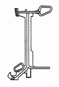
The "900 Amp disconnect switch" (Figure 1) is a solid-blade switch used in a line to provide quick and easy sectionalizing when needed. It is normally equipped with "hooks" to accommodate a portable load break tool and has a solid non-removable blade.
This type of switch offers no line or system protection, and may only be used for sectionalizing purposes, and to pick up or drop load.
Figure 1
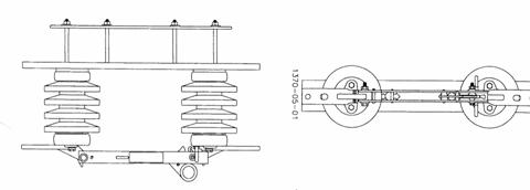
LINE SWITCH
The "line switch" is a distribution cutout that has been fitted with a removable 300 amp solid blade in place of the fuse holder (Figure
2). It is installed the same as the fused cutout and could be of either the conventional or the in-line variation.
Figure 2
This switch type, as the "disconnect switch", offers no system protection, only sectionalizing capabilities. It likewise is constructed to accommodate the load break tool.
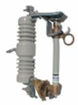
Figure3
In certain instances current limiting fuses are used as well as cutouts to protect the equipment from over-current.The "distribution fused cutout" is the most commonly used switch type. Besides possessing the same sectionalizing capabilities as the other two types, it also offers over current protection and system fuse coordination. Figure 4 shows the pole-mounted distribution fused cutout.
Figure 4
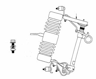
A fused cutout is a one-shot device that automatically isolates a fault then remains open. Most fused cutouts used are of the "drop out" variety. Operation of the fuse link enclosed in a fuse holder collapses the linkage, allowing the fuse or fuse holder to drop out and provide visible and permanent circuit isolation.
Fuse holders rated either 100 or 200 amp may be used. Fuse sizes exceeding 100 amps should never be used in a 100 amp fuse chamber. Likewise fuse sizes less than 125 amp should not be used in the 200 amp chamber. Mismatching of the fuse and fuse chamber will not provide proper arc extinguishing and may become dangerously explosive.
Distribution fused cutouts are also equipped with "hooks" to accommodate a portable load break tool.
Line currents in excess of 15 amps, may only be interrupted safely by the use of a load break tool or by the operation of an up stream oil circuit recloser, or a load-interrupter switch.
Fused cutouts are installed at intervals along the length of a line and its branches to protect distribution equipment and to provide the best possible continuity of service to the largest number of customers.
The fused cutouts protecting the section in which a fault occurs should operate and clear, without damaging or tripping to lock out back-up devices in other sections of the line, nearer to the supply station.
Transformers Transformers come in a wide variety of shapes, sizes and styles. They have a variety of uses. They can step voltage up or down. Station or power transformers are usually very large and capable of handling very large loads. Distribution transformers are smaller and serve residential or small commercial loads. In this section you will learn about the distribution transformer.
|
|
Figure 5
A distribution transformer is a simple, yet complex, piece of equipment. It consists of only a few main parts. There are no moving parts to wear. There are no friction or mechanical losses. However, there is some electrical loss. Most modern transformers are from 96-99% efficient. Many electric utility companies use many sizes of transformers. They are rated in kVA and available in the following sizes. Examples of some are listed below: 1.аааааааа 5ааааааааааааааааааааа 6.аааааааа 37 2.аааааааа 7 1/2ааааааааааааааа 7.аааааааа 50 3.аааааааа 10ааааааааааааааааааа 8.аааааааа 75 4.аааааааа 15ааааааааааааааааааа 9.аааааааа 100 5.аааааааа 25ааааааааааааааааааа 10.аааааа 167 Voltage and Protection A distribution transformer is used to change the voltage from distribution voltage to customer use voltage. Distribution voltages range from 2,400 kV to 19,900 kV (phase to ground) Listed below are some examples:
|
![]()
|
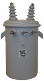
Figure 6
Bushings are mounted into holes in the tank. They are mechanically secured and sealed to the tank. The coil ends exit the tank through the hollow bushings and terminate in a wire holding lug. Primary bushings are shown as "H" on the wiring diagrams. An "X" designates secondary bushings.
|
|
|
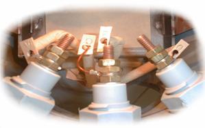
Figure 7а
The primary and secondary coils are fine insulated copper wire wrapped around an iron core. See figure 8. There is no physical connection between the primary and secondary windings. ![]()
![]()
![]()

 |
 |
 |
|||

|

|

|
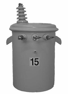
Figure 9
The coils can be connected in series or in parallel, depending on the service requirements. The secondary winding is also rated and insulated for a specific voltage.
|
|
|
|
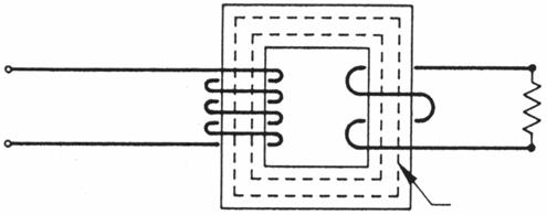
Figure 10
The primary winding is excited with alternating current. The secondary winding receives energy by induction from the primary. The iron core that the coils are wrapped around is made of a soft ferrous metal.
|

Figure 11
Oil is used to insulate and cool the transformer. This oil must be clean and free of moisture. A transformer should never be opened in rain or snow unless protected by a tarp. The tank is made of steel. It is sealed to hold the oil. You can remove the lid to get access to the oil and windings. Installation of complete self-protected (SP) transformers are found in many utility companies. They have a lightning arrester mounted on the transformer tank.а Internally there is a primary fuse and a low voltage ( LV) breaker. This low voltage ( LV) breaker has an external handle that can be operated with a hot stick. The Same CSP transformer is also equipped with a red overload light on the outside of the tank. This can be reset without shutting down the transformer. CSP transformers cannot be used for a 3╪ bank. 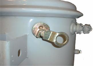
Figure 12
Polarity Polarity of a transformer is simply an indication of direction of current flow from a terminal at any instant. The idea is quite similar to the polarity marking on a battery. In alternating current there is no fixed positive or negative pole, as there is in direct current. Transformers, therefore, only have relative polarities that must be considered. It is important to check the individual transformer nameplates for polarity, especially when dealing with older models.а Polarity is relative and depends on how the leads are brought out. For additive polarity, the H-1 and X-1 bushings are diagonally opposite each other.а For subtractive polarity, the H-1 and X-1 bushings are directly opposite each other. Impedance Impedance is the total opposition offered by a circuit to the flow of current. It is the combined effect of the resistance and the reactance of a circuit. The symbol for impedance is "Z" and it is measured in ohms. Impedance becomes important to you when paralleling or banking transformers.а Match transformers with impedence values within 25% or (+/- .25%) of the lowest value. Note: If the impedance varies greater than 25% the transformer with the lowest impedance will pack most of the load. Transformer Operation Example: We have a distribution transformer with 100 turns of wire in the primary winding.а The energizing voltage is 2,400 volts. Each turns has a potential difference of 2,400 і 100 = 24 volts.
Figure 13
As the primary flux cuts the secondary winding it induces 24 V into each turn.а The number of secondary turns is 10. Secondary voltage = 24 x 10 = 240 volts. Voltage Ratio 2,400/240 = 10/1 Turns Ratio 100/10 = 10/1 Therefore, the more turns in the secondary winding, the higher the voltage induced in this winding. In any transformer the ratio between the primary and secondary voltages is the ratio between the number of turns in the primary and secondary windings. The "current" in the transformer windings varies by the inverse ratio of the "voltage".а This means that in a step-down transformer, the current in the secondary is higher than the current in the primary.а Assuming transformer efficiency to be 100%, in a step-down transformer of 10:1 ratio, the voltage in the primary is ten times the secondary voltage, whereas the current in the primary is only one-tenth the current in the secondary. Therefore, the product of the current and voltage in the primary circuit of a transformer is equal to the product of the current and voltage in the secondary circuit. Example: In an AC circuit, volts x amps = volt-amps |
|||
|
|||
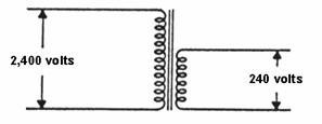
Figure 14
If Primary voltage = 2,400 volts Secondary voltage = 240 volts (Ratio 10:1) Primary current = 10 amps Secondary current = 100 amps (Ratio |
 |
||
![]()
|
|
|
|
|
Figure 15
As mentioned earlier in the section, transformers are rated for certain voltages.а A lineworker must select the transformer to match the primary voltage and provide the desired secondary voltages. The capacity (kVA) rating of the transformer is clearly indicated. The internal impedance is shown as "%Z". If the job requires taps or a dual voltage transformer, this information is on the nameplate as well. Wiring diagrams are shown on the nameplate.а These describe how to connect the secondary coils in parallel or series.а The diagrams also indicate tap changer or dual voltage settings.а "H" is used to indicate the primary winding and "X' is used for the secondary winding on these diagrams. To transport transformers you must know their weight.а |
Figure 16
Every nameplate lists the manufacturer's name and the unit's serial number.а Many plates note the year the unit was built. SKILLS CHECK 1.аааааааа What are three (3) preferred service voltages? ааааааааааааааааааааааа ________________________________________________ ааааааааааааааааааааааа ________________________________________________ ааааааааааааааааааааааа ________________________________________________ 2.аааааааа What device is used to protect transformers from over voltage? ааааааааааааааааааааааа ________________________________________________ 3.аааааааа Are the primary and secondary coils physically connected? ааааааааааааааааааааааа ________________________________________________ 4.аааааааа What two (2) uses does the oil in a transformer serve? ааааааааааааааааааааааа ________________________________________________ ааааааааааааааааааааааа ________________________________________________5.аааааааа Why do you have to check polarity of a transformer when paralleling or banking?
ааааааааааааааааааааааа ________________________________________________ 6.аааааааа You have three (3) transformers to build a 3 phase bank. Their impedance's are:а 2.0; 2.3; and 2.6 Can you use them? ааааааааааааааааааааааа ________________________________________________ ааааааааааааааааааааааа ________________________________________________ 7.аааааааа By what electrical principle does a transformer change the input voltage? ааааааааааааааааааааааа ________________________________________________ 8.аааааааа If a 4,800/240 volt transformer has 5 amps on the primary, what is the secondary current? a)а 200 amps ааааааааааааааааааааааа b)а 100 amps ааааааааааааааааааааааа c)а 50 amps ааааааааааааааааааааааа d)а 400 amps 9.аааааааа If a 14,400/240 V transformer has 160 amps on the secondary, what kVA load is on this transformer? a)а 38.4 kVA ааааааааааааааааааааааа b)а 90 kVA ааааааааааааааааааааааа c)а 19.2 kVA ааааааааааааааааааааааа d)а 9.6 kVA 10.аааааа If you wanted to raise the secondary voltage of a transformer with taps, what setting would you use? ааааааааааааааааааааааа a)а 105% ааааааааааааааааааааааа b)а 100% ааааааааааааааааааааааа c)а 95%11.ааааааааа ааааааааааааааа What setting should a dual voltage transformer be set on when it is shipped from Stores?
ааааааааааааааааааааааа ________________________________________________12.аааааа What does "H" indicate on transformer nameplate wiring diagrams?
ааааааааааааааааааааааа ________________________________________________